15.1 300
Series Stainless Steels
 Orbital welding became practical for many industries
in the early 1980's when combination power supply/control systems were
developed that operated from 240 VAC and were physically small enough to be
carried from place to place on a construction site for multiple in-place welds.
Orbital welding became practical for many industries
in the early 1980's when combination power supply/control systems were
developed that operated from 240 VAC and were physically small enough to be
carried from place to place on a construction site for multiple in-place welds.


To produce high consistent welds the Tungsten electrode must provide the following:
B. Electrode Tip Diameter - Grinding an electrode to a point is sometimes desirable for certain applications, especially where arc starting is difficult or short duration welds on small parts are performed. However in most cases it is best for a welder to leave a flat spot or tip diameter at the end of electrode. This reduces erosion at the thin part of a point and reduces the concern that the tip may fall into the weld. Larger and smaller tip diameters offer the following trade-offs:


Consult electrode charts or a pre-ground electrode supplier to obtain the electrode diameter and tip geometry that is most suitable for your welding application.
 Figure15-8: A Typical Weld Program current Profile
( This weld profile shows a single level of weld time). Orbital welding
normally uses a minimum of 4 levels of weld time with each level decreasing in
weld amperage as the tube heats up during the welding process
Figure15-8: A Typical Weld Program current Profile
( This weld profile shows a single level of weld time). Orbital welding
normally uses a minimum of 4 levels of weld time with each level decreasing in
weld amperage as the tube heats up during the welding process

May be welded by the TIG, MIG, or stick arc-weld
process. TIG welding is recommended as being best for welding Weld fitting
systems because it allows better operator control of heat penetration and
filler material deposition. Stick arc welding is not recommended in many cases
because of the likelihood of excessive burn-through and improper root
penetration. In all cases where stick welding is used, it is recommended that
backing gas be used. MIG welding gives the same characteristics as stick
electrode welding with faster deposition of the filler material.
As this process runs “hotter” than the stick
process, the use of a backing gas is mandatory. It should be noted that in welding
the relatively small fitting sizes, filler deposition rate economies are not a
factor and therefore the MIG method is not commonly applied.
May be welded by the TIG, MIG, stick and
oxyacetylene methods. As scale formation remains a problem, the use of a
backing gas is still recommended.
Carbide Precipitation
When un-stabilized stainless steels are heated to
800° - 1500° F during welding, the chromium in the steel combines with the
carbon to form chrome carbides which tend to form along the grain boundaries of
the metal (carbide precipitation). This lowers the dissolved chromium content
in these areas and thus lowers their corrosion resistance, making them
vulnerable to intergranular corrosion. Carbide precipitation is reduced by
holding the carbon content of the material to a very low value. This limits the
amount of carbon available to combine with the chromium. The “L” series (extra
low carbon) stainless steels are often used for this purpose, but their use
reduces system design stress by approximately 15%. Weld fittings are made from
a select 316 series with carbon content in the low range of 0.04 to 0.07 percent.
This results in a welded fitting with good corrosion resistance and a high strength
factor. All weld fittings in stainless steel are supplied in the solution-treated
condition, capable of passing ASTM-A-262 Tests for Detecting Susceptibility to
Intergranular Corrosion.
The "TIG" in TIG welding stands for
Tungsten Inert Gas. But before it was called TIG" it was given the name
"Heliarc" because helium was the gas that was used when the process
was invented. But then someone discovered that argon worked better and so it
was called TIG because inert gas could refer to either helium or argon. But
wait, then someone else discovered that small additions of hydrogen worked well
for some metals. The word "Inert" no longer held true so it was
decided that a new name was required. So nowadays, the technical term for what
used to be called ‘TIG’ and ‘Heliarc’ is Gas Tungsten Arc Welding or
"GTAW". People still call it TIG and even Heliarc. In fact more
people call it TIG welding than Gas Tungsten Arc Welding.
TIG welding is akin to gas welding as far as
welding technique in that the torch is held in one hand and the filler rod is
manipulated with the other hand. It is considered more difficult than other arc
welding processes because it requires the use of both hands. Often times a foot
pedal amperage control is also used which adds another layer of difficulty.
A TIG torch can be either water cooled or air
cooled and is designed to provide shielding gas as well as welding current
through a tungsten electrode. A ceramic nozzle directs the shielding gas to the
weld puddle and internal copper parts like the collet and collet body hold the
electrode in place. The tungsten electrode is sharpened for applications where
the arc needs to be pinpointed and for very low amperage. The heat the melts
the metal and makes the weld puddle comes from the arc that is created between
the tungsten electrode and the work piece. The arc is shielded by argon,
helium, or a mixture of the two. Sometimes for certain alloys, hydrogen is
added in small percentages to improve the way the puddle flows. The arc is very
smooth and quiet and clean when DC current is used. When the TIG welding
machine is set on Alternating current, it is slightly more noisy but still
clean and smooth.
What Metals can be welded using the TIG process?
Almost any metal can be welded with TIG. Carbon and
low alloys steels like 1010 carbon steel and 4130 chromoly steel, Stainless
steels like 304, 321, and 17-7ph, Nickel alloys like inconel 718 and Hastelloy
X, Aluminum alloys like 6061, 5052, Magnesium alloys like az31b, Titanium
alloys like commercially pure, and 6al4v, Cobalt alloys like Stellite 6b and
l605, copper alloys like Nibral bronze and pure copper, All can be welding
using the TIG welding process.
Orbital welding was first used in the 1960's when
the aerospace industry recognized the need for a superior joining technique for
aerospace hydraulic lines. A mechanism was developed in which the arc from a
tungsten electrode was rotated around the tubing weld joint. The arc welding
current was regulated with a control system thus automating the entire process.
The result was a more precision and reliable method than the manual welding method it
replaced.
Modern day orbital welding systems offer computer control
where welding parameters for a variety of applications can be stored in memory and called up when
needed for a specific application. The skills of a certified welder are thus built into the welding system,
producing enormous numbers of identical welds and leaving significantly less
room for error or defects.

In the orbital welding process, tubes/pipes are
clamped in place and an orbital weldhead rotates an electrode and electric arc
around the weld joint to make the required weld. An orbital welding system
consists of a power supply and an orbital weldhead.
Power Supply: The power supply/control system
supplies and controls the welding parameters according to the specific weld
program created or recalled from memory. The power supply provides the control
parameters, the arc welding current, the power to drive the motor in the weld
head and switches the shield gas(es) on/off as necessary.
Weld Head: Orbital weld heads are normally of the
enclosed type and provide an inert atmosphere chamber that surrounds the weld
joint. Standard enclosed orbital weld heads are practical in welding tube sizes
from 1/16 inch (1.6mm) to 6 inches (152mm) with wall thickness' of up to .154
inches (3.9mm) Larger diameters and wall thickness' can be accommodated with
open style weld heads.
There are many reasons for using orbital welding
equipment. The ability to make high quality, consistent welds repeatedly at a
speed close to the maximum weld speed offer many benefits to the user:
Productivity. An orbital welding system will
drastically outperform manual welders, many times paying for the cost of the
orbital equipment in a single job.
Quality. The quality of a weld created by an
orbital welding system with the correct weld program will be superior to that
of manual welding. In applications such as semiconductor or pharmaceutical tube
welding, orbital welding is the only means to reach the weld quality
requirements.
Consistency. Once a weld program has been
established an orbital welding system can repeatedly perform the same weld
hundreds of times, eliminating the normal variability, inconsistencies, errors
and defects of manual welding.
Skill level. Certified welders are increasingly
hard to find. With orbital welding equipment you don't need a certified welding
operator. All it takes is a skilled mechanic with some weld training.
Orbital welding may be used in applications where a
tube or pipe to be welded cannot be rotated or where rotation of the part is
not practical.
Orbital welding may be used in applications where
access space restrictions limit the physical size of the welding device. Weld
heads may be used in rows of boiler tubing where it would be difficult for a
manual welder to use a welding torch or view the weld joint.
Many other reasons exist for the use of orbital
equipment over manual welding. Examples are applications where inspection of
the internal weld is not practical for each weld created. By making a sample
weld coupon that passes certification, the logic holds that if the sample weld
is acceptable, that successive welds created by an automatic machine
with the same input parameters should also be sound.
Aerospace: As noted earlier, the aerospace industry
was the first industry to recognize the requirement for orbital welding. The
high pressure systems of a single plane can have over 1,500 welded joints, all
automatically created with orbital equipment.
Boiler Tube: Boiler tube installation and repairs
offer a perfect application for orbital welding. Compact orbital weld heads can
be clamped in place between rows of heat exchanger tubing where a manual welder
would experience severe difficulty making repeatable welds.
Food, Dairy and Beverage Industries: The food,
dairy and beverage industries require consistent full penetration welds on all
weld joints. Most of these tubing/piping systems have schedules for cleaning
and sterilization in place. For maximum piping system efficiency the tubing
must be as smooth as possible. Any pit, crevice, crack or incomplete weld joint
can form a place for the fluid inside the tubing to be trapped and form a
bacteria harbor. Nuclear Piping/Tubing: The nuclear industry with its severe
operating environment and associated specifications for high quality welds has
long been an advocate of orbital welding.
Offshore Applications: Sub-sea hydraulic lines use
materials whose properties can be altered during the thermal changes that are
normal with a weld cycle. Hydraulic joints welded with orbital equipment offer
superior corrosion resistance and mechanical properties.
Pharmaceutical Industry: Pharmaceutical process
lines and piping systems deliver high quality water to their processes. This
requires high quality welds to ensure a source of water from the tubes that is
uncontaminated by bacteria, rust or other contaminant. Orbital welding ensures
full penetration welds with no overheating occurring that could undermine the
corrosion resistance of the final weld zone.
Semiconductor Industry: The semiconductor industry
requires piping/tubing systems with extremely smooth internal surface finish in
order to prevent contaminant buildup on the tubing walls or weld joints. Once
large enough, a build up of particulate, moisture or contaminant could release
and ruin the batch process.
Tube/Pipe Fittings, Valves and Regulators:
Hydraulic lines, and liquid and gas delivery systems all require tubing with
connector fittings. Orbital systems provide a means to ensure high productivity
of welding and improved weld quality. Sometimes the tubing may be welded in
place to a valve or regulator body. Here the orbital weldhead provides the
ability to produce high quality welds in applications with restricted access to
the weld joint.
For orbital welding in many precision or high
purity applications, the base material to be welded, the tube diameter(s), weld
joint and part fit -up requirements, shield gas type and purity, arc length,
and tungsten electrode material, tip geometry and surface condition may already
be written into a specification covering the specific application.
Each orbital welding equipment supplier differs
slightly in recommended welding practices and procedures. Where possible,
follow the recommendations of your orbital equipment supplier for equipment
set-up and use, especially in areas that pertain to warranty issues.
This section is intended as a guideline for those
applications where no specification exists and the engineer responsible for the
welding must create the welding set-up, and derive the welding parameters in
order to arrive at the optimum welding solution.
The orbital welding process uses the Gas Tungsten
Arc Welding process (GTAW) as the source of the electric arc that melts the
base material and forms the weld. In the GTAW process (also referred to as the
Tungsten Inert Gas process - TIG) an electric arc is established between a
Tungsten electrode and the part to be welded. To start the arc, an RF or high
voltage signal (usually 3.5 to 7 KV) is used to break down (ionize) the
insulation properties of the shield gas and make it electrically conductive in
order to pass through a tiny amount of current. A capacitor dumps current into
this electrical path, which reduces the arc voltage to a level where the power
supply can then supply current for the arc. The power supply responds to the demand
and provides weld current to keep the arc established. The metal to be welded
is melted by the intense heat of the arc and fuses together. No additional filler
material is used in this process of welding.
The material selected varies according to the
application and environment the tubing must survive. The mechanical, thermal,
stability, and corrosion resistance requirements of the application will
dictate the material chosen. For complex applications a significant amount of
testing will be necessary to ensure the long term suitability of the chosen
material from a functionality and cost viewpoint.
In general, the most commonly used 300 series
stainless steels have a high degree of weldability with the exception of
303/303SE which contain additives for ease of machining. 400 series stainless
steels are often weldable but may require post weld heat treatment.
Accommodation must be made for the potential
differences of different material heats. The chemical composition of each heat
batch number will have minor differences in the concentration of alloying and
trace elements. These trace elements can vary the conductivity and melting
characteristics slightly for each heat. When a change in heat number is made a
test coupon should be made for the new heat. Minor changes in amperage may be
required to return the weld to its original profile.

It is important that certain elements of the
material be held to close tolerances. Minor deviations in elements such as
sulfur can vary the fluid flow in the weld pool thus completely changing the
weld profile and also causing arc wander.
Weld joint fit-up is dependent on the weld
specification requirements on tube straightness, weld concavity, reinforcement
and drop through. If no specification exists the laws of physics will require
that the molten material flow and compensate for tube mismatch and any gap in
the weld joint.
Tubing is produced according to tolerances that are
rigid or loose according to the application for which the tube was purchased.
It is important that the wall thickness is repeatable at the weld joint from
part to part . Differences in tube diameter or out -of-roundness will cause
weld joint mismatch and arc gap variations from one welding set up to another.
Tube and pipe end prep facing equipment is
recommended in order to help ensure end squareness and end flatness. Both the
ID and OD should be burr free with no chamfer.
When two tubes are butted together for welding, two
of the main considerations are mismatch and gaps. In general, the following
rules apply:
Any gap should be less than 5% of the wall
thickness. It is possible to weld with gaps of up to 10% (or greater) of wall
thickness, but the resultant quality of weld will suffer greatly and
repeatability will also become a significant challenge.
Wall thickness variations at the weld zone should
not be more than ± 5% of nominal wall thickness. Again, the laws of physics
will allow welding with mismatch of up to 25% of wall thickness if this is the only
challenge but again, the resultant quality of weld will suffer greatly and
repeatability will also become a significant issue.
Alignment mismatch (high-low) should be avoided by
using engineering stands and clamps to align the two tubes to be welded. This
system also removes the mechanical requirement of aligning the tubes from the
orbital weldhead.
An inert gas is required on the tube OD and ID
during welding to prevent the molten material from combining with the oxygen in
the ambient atmosphere. The objective of the welder should be to create a weld
which has zero tint at the weld zone ID.
Argon is the most commonly used shield gas (for the
OD of the tube)and the purge gas (for the ID of the tube). Helium is often used
for welding on copper material. Mixed gases such as 98% Argon/2% Hydrogen, 95%
Argon/5% Hydrogen, 90% Argon/10% Hydrogen or 75% Helium/25% Argon may be used
when the wall thickness to be welded is heavy (.1" or above). Using
mixtures of 95% Argon/5% Hydrogen is incompatible with carbon steels and some
exotic alloys, often causing hydrogen embrittlement in the resultant weld. As a
general rule use 100% argon gas, for simplicity and reduction of shield gas cost.
Gas purity is dictated by the application. For high
purity situations where the concern for micro-contamination is paramount, such
as semiconductor and pharmaceutical applications, the shield and purge gases
must minimize the heat tint that could otherwise be undesirable. In these
applications, ultra high purity gas or gas with a local purifier are employed.
For non-critical applications, commercial
grade argon gas may be used.
The tungsten welding electrode, the source of the
welding arc, is one of the most important elements of the welding system that
is most commonly ignored by welding systems users. While no one would refute
the importance of the ignition device on an automobile airbag, the rip cord for
a parachute, or quality tires for automobiles, the importance of tungsten
electrode for quality welding is often overlooked. Users continue to manually
grind and wonder why they produce inconsistent results. Whether in manual or
automatic welding, this is the area where manufacturing organizations can
improve the consistency of their welding output with minor effort.
The objective for the choice of tungsten parameters
is to balance the benefits of a clean arc start and reduced arc wander with
good weld penetration and a satisfactory electrode life.
Electrode
Materials: For quite some time, tungsten manufacturers have added an oxide
to pure tungsten to improve the arc starting characteristics and the longevity of
pure tungsten electrodes. In the orbital welding industry, the most commonly used
electrode materials are 2% thoriated tungsten and 2% ceriated tungsten.
Safety:
The safety issues of tungsten electrode material are now being looked at more
closely. Many users of the TIG welding process do not realize that the welding electrode
they use contains Thorium, a radioactive element added to the tungsten. While
the radioactivity is of a low level, it brings an issue of danger especially
with the radioactive dust generated when grinding the electrodes to a point for
welding.
Alternative, non-radioactive tungsten materials are
now available, such as 2% ceriated electrodes, which often offer superior arc
welding. While these materials are commercially available they have been
largely ignored until recently.
Recommended
Electrode Materials: Cerium, as a base material, has a lower work function
than thorium, thus it offers superior emission characteristics. Thus, not only
do ceriated electrodes offer an advance in electrode safety, they also improve the
arc starting ability of the orbital equipment. However, as mentioned earlier,
it is always best to follow the advice of your orbital equipment manufacturer.
2%
ceriated and 2% thoriated electrodes are the most
commonly recommended materials for orbital welding equipment.
Electrode Tip
Geometry: Given the ever increasing weld quality requirements of the final
weld, more and more companies are looking for ways to ensure that their weld
quality is up to par. Consistency and repeatability are key to welding applications.
The shape and quality of the tungsten electrode tip is finally being recognized
as a vital process variable. Once a weld procedure has been established, it is
important that consistent electrode material, tip geometry and surface condition
be used.
Figure-15-5: Weld Electrode tip diameter

To produce high consistent welds the Tungsten electrode must provide the following:
1. High quality electrode material
2. The electrode tip dimensions shown must be held
to close tolerances
3. The surface finish (ground or polished) of the
electrode grind must be consistent.
Welders should follow an equipment supplier's
suggested procedures and dimensions first, because they have usually performed
a significant amount of qualifying and troubleshooting work to optimize
electrode preparation for their equipment. However, where these specifications
do not exist or the welder or engineer would like to change those settings to
possibly improve and optimize their welding, the following guidelines apply:
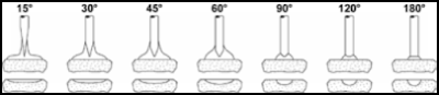
A. Electrode
Taper - This is usually called out in degrees of included angle (usually
anywhere between 14º and 60º). Below is a summary
chart that illustrates how
different tapers offer different arc shapes and
features:
In addition, to demonstrate graphically how the
taper selection will affect the size of the weld bead and the amount of
penetration, below is a drawing that shows typical representations of the arc
shape and resultant weld profile for different tapers.

B. Electrode Tip Diameter - Grinding an electrode to a point is sometimes desirable for certain applications, especially where arc starting is difficult or short duration welds on small parts are performed. However in most cases it is best for a welder to leave a flat spot or tip diameter at the end of electrode. This reduces erosion at the thin part of a point and reduces the concern that the tip may fall into the weld. Larger and smaller tip diameters offer the following trade-offs:

Tungsten Electrode Grinders and Pre-Ground
Electrodes: Using electrodes pre-ground to requirements or a dedicated
commercial electrode grinder to provide electrode tip quality and consistency
offers the following benefits to the user in their welding process:
1. Improved arc starting, increased arc stability
and more consistent weld penetration.
2. Longer electrode life before electrode wear or
contamination.
3. Reduction of tungsten shedding. This minimizes
the possibility of Tungsten inclusions in the weld.
4. A dedicated electrode grinder helps ensure that
the welding electrodes will not become contaminated by residue or material left
on a standard shop grinder wheel.
5. Tungsten electrode grinding equipment requires
less skill to ensure that the tungsten electrode is ground correctly and with
more consistency.
Pre-Ground Electrodes: Rather than risk electrode
radioactivity issues and also constantly endure the variability of each
operator grinding the electrodes with a slightly different touch, many
manufacturing organizations have chosen to purchase electrodes pre-ground. In
addition, since a small difference in the
dimensions of an orbital electrode can produce a
big difference in the weld results, pre-ground electrodes are the preferred
electrode choice to maintain the consistency of your welding. This low cost
option ensures that the electrode material quality, tip geometry and ground
electrode surface input to the welding process is constant.
Consult electrode charts or a pre-ground electrode supplier to obtain the electrode diameter and tip geometry that is most suitable for your welding application.
Figure-15-7: Using pre -ground electrodes ensure
that the elect rode material quality, tip geometry and ground electrode surface
input to the welding process is constant
Many welding equipment suppliers offer a series of
pre-calculated weld programs for a variety of tube diameters, wall thicknesses
and materials. Welders should always follow an equipment supplier's suggested
procedures first, because they have usually performed a significant amount of
qualifying and troubleshooting work to optimize electrode preparation for their
equipment.
However, it is impossible for the equipment
suppliers to have welding procedures for every welding application and there
will always exist a trade off in maximum weld speed possible versus weld
quality and repeatability. Where weld parameter specifications do not exist or
the welder or engineer would like to change those settings to possibly improve
or optimize their welding, the guidelines noted below
give information on how to modify the welding
parameters for a desired result.
Note: The "rules of thumb" noted below
are general guidelines only and will not apply to every welding application and
mix of parameters chosen. Although the welding parameters are often chosen and
changed according to the specific needs of the application, there are some
industry standards that have been developed as starting points. Experimentation
and experience will determine the final weld parameters.
Arc Length
The arc gap setting is dependent on weld current,
arc stability and tube concentricity/ovality. The objective of the welding
engineer is to keep the electrode at a constant distance from the tube surface
with sufficient gap to avoid stubbing out.
As a "rule of thumb" use a base arc gap
of 0.010" and add to this half the penetration required (usually the tube
wall thickness) expressed in thousandths of an inch. Thus if the tube wall is
.030" then a good starting arc gap would be 0.010" + 0.015" =
.025". For a wall thickness/penetration requirement of .154" the arc
gap would be 0.010" + .070" = 0.080"
Weld Speed
The weld speed is dependent on flow rate of
material to be welded, and wall thickness. The objective is to weld as fast as
possible while still yielding a quality output.
As a starting point the tungsten surface speed
should be 4 - 10 inches per minute with the faster welding speeds used for
thinner wall materials and the slower welding speeds used for heavy wall
thickness. As a good starting point, use 5 inches per minute.
Welding Current
The welding current is dependent on the material to
be welded, wall thickness, weld speed, and the shield gas chosen. The objective
is to achieve full penetration, defect free welds.
As a starting point use 1 ampere current per
0.001" wall thickness if the material is stainless steel. Thus for a
0.030" wall tubing the average weld current will be 30 amps in the first
level.
Weld Current Levels
Orbital welding normally uses multiple levels of
weld current to compensate for heat building up in the tube during the welding
process. If the weld current used to initially penetrate the tubing was held at
the same level for the complete weld, the weld penetration would increase as
the weld progressed around the tube, producing too much penetration.

Normally orbital welding uses a minimum of 4 levels
of weld time with each level decreasing in weld amperage Starting parameters:
Set weld level 4 to be at 80% of weld level 1 amperages. Set weld level 2 and
weld level 3 to gradually decrease the current from level 1 to level 4.
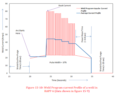
Figures 15-9 and 15-10 depict a typical weld
program current profile for a 10 mm O.D. SS tube. It may be noted that in the
weld program chosen by the welder, the time for each level is same (Impulse
rate) and the average current decreases with each level.
Arc Pulsing
Arc pulsing involves using the welding power supply
to rapidly alternate the weld current from a high (peak current) to a low
(background current) value. This creates a seam of overlapping spot welds. This
technique reduces the overall heat input to the base material and can also
allow for increases in weld speed. This welding technique brings many benefits
to the welding procedure, often improving weld quality and repeatability. In some
cases materials and weld joints with poor fit-up that are difficult to
successfully weld with a non-pulsed arc can easily be welded with a pulsed arc
technique. The result is improved weld quality and increased output.

Figure 15-9: Weld program data sheet of a typical
weld in RAPP-6

In orbital welding, arc pulsing also offers another
advantage due to the fact that the gravity pulls the weld puddle in different
directions as the weld is created around the tube. When pulsing at peak current
the base material(s) melt and flow together, at the lower background current
the puddle can solidify before becoming liquid at the next peak current pulse.
This diminishes the effect of gravity on the molten weld, minimizes the weld
sagging at the 12 and 6 o clock positions, and reduces the molten weld puddle
running/slumping downhill at the 3 and 9 o'clock positions and effectively
alters the electrode to weld puddle distance. The arc pulsing technique thus
becomes more advantageous as the wall thickness
increases resulting in a larger weld puddle.
Arc Pulsing Parameters: Arc pulsing involves four
welding parameters: peak current, background current, pulse width (duty cycle),
and pulse frequency. Here again, opinions vary from one welding organization to
another and indeed from welder to welder. Many welders arrive at the same
welding result having somewhat different welding parameters.
It is important to understand how to choose
convenient weld development starting parameters and the effect on the weld by
changing each parameter. The primary objective is to use the benefits of weld
pulsation to improve weld quality and output.
Peak/Background Current Ratios: The peak to
background current ratios basically provides a means for the welding current to
pulse from one level to another. Industry usage generally varies from 2:1
ratios to 5:1 ratios. A good starting point is to use 3:1 ratios, make the
required weld and test other parameters to see if any benefit can be gained.
Pulse Frequency: The pulse frequency is dependent
on spot overlap required. Good starting parameters are to attempt for a 75%
spot overlap. Pulse rate for thin wall tube is often equal to the weld speed in
ipm (5 ipm = 5 pps) {pps: pulse per second}
Pulse Width: The pulse width (the percentage of
time spent on the peak current) is dependent on heat sensitivity of material
and available current from power supply. Higher heat sensitivity requires lower
pulse width % on peak current. Standard pulse widths are often 20% to 50%. A
good starting parameters would be to set a pulse width of 35%.
Welding Parameter Development Example for
1" Tube/.030" Tube Wall Thickness:
1. Arc Length/Gap = .010" + (0.5 x penetration
required)
Starting Parameters: .010" + (0.5 x
.030") = .025"
2. Weld Speed = 5 ipm surface speed
RPM = ipm/(3.1415 x dia.)
Starting Parameters: 5/(3.1415 x 1") = 1.59
RPM
3. Welding Current Levels
Level 1 = 1 amp per .001" of wall thickness
for level 1 current
Level 4 = 80% of Level 1 current
Levels 2 and 3 gradually decrease the current from
Level 1 to Level 4
Starting Parameters:
Level 1 Peak Current = .030" wall thickness =
30 amps
Level 4 Peak Current = 30 amps x 80% = 24 amps
Level 2 Peak Current = 28 amps
Level 3 Peak Current = 26 amps
Background Current will be 1/3rd of peak current.
Pulse width/duty cycle is 35%
4. Tungsten Electrode Diameter & Tip Geometry -
Use your equipment manufacturer's specifications or consult your pre-ground
electrode supplier
The above data gives starting parameters. On
completion of the first test weld, the parameters will be modified to obtain
the final result desired.
Yes i am totally agreed with this article and i just want say that this article is very nice and very informative article.I will make sure to be reading your blog more. You made a good point but I can't help but wonder, what about the other side? !!!!!!THANKS!!!!!!
ReplyDeleteRobinets de Lavabo
Thanks for share this post,
ReplyDeleteWelders can vary greatly between models and types . Learn about the getting a Welder and what to look for in buying a Welder.
Its really wonderful post your have shared here, I have bookmarked your blog for the future references. Keep posting the article on this topics.We are manufacturers of Trucks & trolley's. Have a look at Welding Rotators
ReplyDeleteNice post,
ReplyDeleteI have got many information from your blog, that is very interesting and informative. Thank you so much...
stainless steel pipes and fittings in UAE
Wow :)
ReplyDeleteThis is an incredible collection of ideas!
Waiting for more helpful pieces.
You would amazing to read a similar one here-
bestofweldings blog
Wow :)
ReplyDeleteThis is an incredible collection of ideas!
Waiting for more helpful pieces.
You would amazing to read a similar one here-
Besttoolsbrand
Insanely comprehensive :)
ReplyDeleteThank you so much,
Now I have something to read during the holidays. This will take a while but well worth it like always
You can read another one here Besttoolsbrand
Your blog is very informative and good. Its help me a lot. If you cutting thick metal can be extremely difficult without the right set of tools. If you are facing the challenging tasks of cutting metal quickly with precision and consistency, then https://weldingtoolsgeek.com/best-plasma-cutters/ , is the right tool for your needs.
ReplyDeleteYour blog is very informative and good. Its help me a lot. If you cutting thick metal can be extremely difficult without the right set of tools. If you are facing the challenging tasks of cutting metal quickly with precision and consistency, then https://weldingtoolsgeek.com/best-plasma-cutters/ , is the right tool for your needs.
ReplyDeleteYou will put yourself in serious risk if you are welding without wearing gloves. Welders are exposed to extreme temperatures from which they need ample protection. To help you find the right gloves for your welding needs, we have selected a variety of high-quality Best Welding Gloves Reviews suited to different applications. Here you can find the best welding gloves and it will be helpful for you to choose the best one.
ReplyDeleteThe reason you want to choose the correct machine depends on your specific needs.While there is many TIG Welders available, there are some that work better with certain metals than others. Source to know more about best tig welder.
ReplyDeleteThank you for such great information. Those well defined welding methods going to help many a lot.
ReplyDeletei really like your content Best Welding Helmet
ReplyDeleteStainless Steel Flat bar Dealer in Ahmedabad
ReplyDeleteDiamond metal is one the best Manufacturer and dealers for stainless steel raw material And flat bar dealers in ahmedabad and Stainless steel Pipe and fittings and flange Manufacturer in Ahmedabad S S Plate Dealer in Ahmedabad Gujarat India.
Great blog, learned many things about welding machines from this blog, very informative. Pacific weld is one of the best places to buy welding machine in India.
ReplyDeleteAutomated Manufacturing System
Manufacturing Automation
Spm Machine Tools
Welding Robotic Arm
Great Yuva Welding Machines
Seam Welding Machine
Thank you so much to share such an amazing and informative article. Keep us updating with more interesting articles. Also, visit at piping insulation for commercial pipes.
ReplyDeleteElectric resistance welding
ReplyDeleteThe world owes the invention of electric resistance and spot welding to Englishman Elihu Thomson. This engineer has several patents in the field of spot welding to his name.
Electric resistance welding consists in assembling by autogenous fusion the parts to be welded under the pressure of two metal parts. Who says welding says heat, with resistance welding the heat necessary for welding is provided by the Joule effect (which is the thermal manifestation of electrical resistance, this heat occurs when an electric current passes through any material conductor) of a current of high intensity and low voltage, passing through the parts to be assembled. Indeed, it takes a lot of amps and little voltage. The application of a forging force makes it possible to ensure the metallic interpenetration.
resistance welding
This comment has been removed by the author.
ReplyDeleteVery informative post, thanks for sharing! However, if you want to buy the best welding machine in Miami then you can visit the Service Welding Supply website. Here you'll find the best welding machines at the most competitive price.
ReplyDeleteI really like this blog information, it is very useful content posting. Thank you very much for sharing on Google Safe Search Browsing. Know about Petron Thermoplast.
DeleteThanks for Sharing this Blog! Buy welding supplies online from The Haggarty Group Qld Pty Ltd to handle your welding needs better. Check the products you need for your project.
ReplyDeleteawesome post presented by you..your writing style is fabulous and keep update with your blogs. expansion joints suppliers in uae
ReplyDeleteWelding is a great technique to join metals.
ReplyDelete
ReplyDeleteWhen it comes to welding certifications needed and metalworking, there are certain credentials that are required in order to be a successful technician. One of these credentials is the AWS welding certification. AWS welding certification is a program that was created by the American Welding Society in order to certify welders who are able to work with a variety of metals and welding processes.
Very nice post...Awesome cover all methods of welding
ReplyDeleteWelding Consumables Manufacturers in India
welding electrodes suppliers in india
Keep sharing such informative posts. Best valves and strainers supplier offers Pipe Fittings. We offer high quality Pipe Fittings at low cost.
ReplyDeleteJacketed Plug Valve manufacturers
pipe welder...... read more
ReplyDeletePipe Welder school
Nice and great post Thanks for sharing
ReplyDeleteWelding is one of the most common metalworking occupations. It’s a process of joining pieces of metal by heating them up and then welding them together. Welding is an important skill Pipe Welder school
OUTLAW LEATHER HOOD
Weldmate is a top supplier of best quality welding machine, plasma machine, mig tig torch, plasma etc. We delivered at Ludhiana, Amritsar, Jalandhar and all over India. Read more: welding machine in Ludhiana
ReplyDeleteThis is very informative. keep up the good work. to shopping tools for welding visit Weldmate.
ReplyDeleteLeaving your website was out of the question without mentioning how impressed I was by the high-quality information you present about Commercial Pipes to your readers. I'll be a frequent visitor to stay updated on your upcoming content.
ReplyDeleteAmazing information about welding methods Private Tutor Greater Heights
ReplyDeleteThanks for sharing welding methods Private Tutor Bouldin Creek
ReplyDeleteIts such an amazing post, really helpful and informative for sure, keep sharing such blogs.
ReplyDeleteindium Oxide ( In2O3)
This comment has been removed by the author.
ReplyDeleteGood welding methods world equestrian center tutors
ReplyDeleteThis article provides a clear and informative overview of various welding techniques, highlighting the importance of Welding Parameters in achieving high-quality welds. The focus on TIG and orbital welding, along with their industrial applications, makes it a valuable resource for professionals seeking precision and consistency in their work.
ReplyDeleteVery informative post! Multi-process welders save so much space and time by combining multiple functions. I found a really helpful article recently that compares the top models under $1000, which could be great for anyone considering making a purchase soon.
ReplyDeleteThis article offers great insights into welding techniques. I’ve been learning about stick welding recently, and it’s amazing how versatile this method is for various applications. For beginners looking to dive deeper, I found this stick welding guide really helpful!
ReplyDeleteI appreciate your article on multi-process welders. It’s so helpful for people who want versatility without breaking the bank. Your section on the drawbacks of multi-process welders was very balanced. Could you include some tips on maintaining these machines to ensure durability?
ReplyDeleteYou are a great writer. I like the way you present it. Surely, it helps a lot. Thanks for this and keep writing.
ReplyDeleteWelding machine Manufacturer and Supplier in Ludhiana
Thank you so much for sharing this informative post. Really i got exact information what i was searching Industrial Welding to know about our service.
ReplyDeleteThis post is extremely helpful for anyone wanting to understand Electrofusion welding better. Clear explanations and useful insights throughout.
ReplyDeleteAre you in need of a skilled Electrofusion Welder Melbourne area? Your search ends here. At L.D. Smith Plumbing & Gasfitting, we take pride in offering high-quality plumbing and gasfitting services focusing on quality and creativity.