10.1 Best practices for impulse tubing installation

Tube Positioning Rules
 Compensate for springback:
 Tube Stretch or Pickup
 NOTE:
NOTE:
 Pre-Measuring


STEP 2 Next, determine the angle of offset - 30° or 45°. The latter (45°) is recommended because benders are calibrated for 45° bending.
STEP 3 Figure the length of the tube required to meet your offset requirements (“L” dimension) in the diagram. For 30° bends multiply desired offset “F”x 2= 30° offset dimension “L”. For 45° bends multiply desired offset “F”x 1414=45° offset dimension “L”.
STEP 4 Determine where you want the offset bend of the tube to start; and make a reference mark (A). Now measure off the “L” dimension (determined in Step 3), starting from the reference mark and make a second mark (B). You are now ready to make the bends.
STEP 5 Align mark (A) with reference mark 45° on bender shoe handle (measurement end to the left) and proceed with first bend. Then align (B) with 45° mark and make second bend in proper direction (measurement end to the left). Follow previous detailed instructions for making 45° bends in one plane.
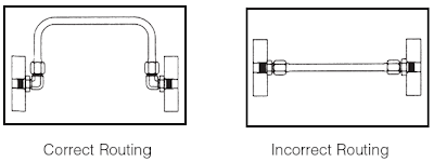


Allow for expansion and contraction - Use a “U” bend in long lines to
allow for expansion and contraction.


Have a neat appearance and allow for easy trouble shooting, maintenance and repair.

 Because of its exceptional formability, copper can be formed as desired
at the job site. Copper tube, properly bent, will not collapse on the outside
of the bend and will not buckle on the inside of the
Because of its exceptional formability, copper can be formed as desired
at the job site. Copper tube, properly bent, will not collapse on the outside
of the bend and will not buckle on the inside of the

- Separation between redundant instrument sensing lines should be provided by free air space or barriers or both such that no single failure can cause the failure of more than one redundant sensing line.
- The minimum separation between redundant sensing lines should be at least 450 mm. As an alternate a suitable steel or concrete barrier can be used.
- Instrument sensing lines should be run along the walls, columns or ceilings wherever practicable, avoiding open or exposed area to decrease the likelihood of persons supporting themselves on the lines or of damage to the sensing lines by pipe whip, jet forces or falling objects.
- Routing of instrument sensing lines should ensure that the lines are not subjected to vibrations, abnormal heat or stress.
- Where redundant instrument sensing lines penetrate a wall or floor the required separation (Minimum 450 mm) should be maintained. Care should be taken to ensure that the tubing/piping does not rest on or against any abrasive surface.
- They should be kept as short as possible. This is good for two reasons;
- The speed of response is reduced for long runs
- Resonance frequency is increased for longer tube runs. This is detrimental from vibratory and seismic considerations.
- The distance of transmission for instrumentation tubing should be limited to 16 meters only. Beyond this limit electrical or pneumatic transmission should be used.
- They should not cause any obstructions that would prohibit personnel or traffic access.
- They should not interfere with the accessibility for maintenance of other items of equipment/instrument.
- They should avoid hot environments or potential fire risk area.
- Sensing lines should be located with sufficient clearance to permit sagging.
- The two impulse lines especially in case of ΔP /flow measurements should be kept close together to avoid a false pressure difference arising from a difference in temperature.
- There should be provision for thermal expansion and contraction preferably by tube/pipe bends, elbows, offsets or changes in direction of sensing lines.
- The number of joints should be kept to a minimum.
- Sensing lines should be adequately supported along its entire length.
- Supports, brackets, clips, or hangers shall not be fastened to the instrument sensing lines for the purpose of supporting cable trays or any other equipment.
- Sensing lines should continuously slope downwards towards the sensing instruments in case of liquid and upwards in case of gases. The slope should not be less than 1:12. The slope should be increased if the liquid in impulse lines is more viscous than water.
- Bends rather than fittings should be used to change the direction of a run of piping or tubing. A bending tool should be used when bending the tubing in cold condition. Fittings are permitted where the use of bends is not practical.
- Sharp bends should be avoided.
- While installing the sensing lines the bend radius of tubing should not be less than 3 Do.
- Tubes at different temperatures should not be run together for level measurement. This may affect the density of fluid in reference or measurement legs.
- The instrument sensing tubing or piping runs pertaining to a nuclear safety-related instrument channel should be identified and coded so as to identify its channel.
- Each instrument-sensing line and associated valves in this channel should have an identification tag showing the channel and unique line or valve identification number.
- If multiple sensing lines are installed in a single tray, the tray should be identified with the appropriate sensing line numbers, colors, etc.
- Each instrument sensing line, as a minimum, should be tagged at its process line root-valve connection, at the instrument, and at any point in between where the sensing line passes through a wall or a floor (on both sides of such penetration). Each valve also should be tagged.
- Where tubing penetrates a radiation, fire, water, or air seal, care should be taken to ensure that the seal is not degraded by the sensing line's seismic or thermal movements. In addition, the mechanical properties of the seal shall be reviewed to ensure that the seal does not anchor the sensing line when a guide is required.
- All sensing lines including trays, supports, instrumentation, valves, and other in-line devices should be installed to avoid contact interferences caused by relative motion between the sensing line and other adjacent equipment or devices. Sources of relative motion that should be considered are thermal expansion, seismic motions, vibrations, and design-basis accidents or events. The Code classification of the sensing line will determine the requirements for relative motion that shall be considered.
- Routing of the nuclear safety-related sensing lines shall ensure that the function of these lines is not affected by thermal motions due to “hot blow down” of the sensing lines.
- One of the following methods should be used to ensure that the sensing-line function is not affected:
- Demonstrate by documented analysis or calculations that the majority of the sensing line routing is at ambient temperature, and “hot blow down” is not a design loading.
- Or
- Design the sensing line routing using the process design temperature as the temperature value used in the design analysis.
- Routing of the nuclear safety-related sensing lines shall ensure that the function of these lines is not affected by the movement of the main process (piping, ductwork, equipment, etc.) to which the sensing line is connected.
- One of the following methods should be used to ensure that the sensing line function is not affected:
- Demonstrate by documented analysis or calculations that the process movements are negligible.
- Or
- Demonstrate by documented analysis or calculations that sufficient flexibility has been provided to accommodate the process movements.
- Flexible hose may be used in sensing lines to accommodate the process thermal, seismic, and vibrational movements if its ratings equal or exceed the design requirements, including service life. Installation considerations should include maintaining slope and no low points.
- Instrument sensing lines and accessories inside the Containment Building shall withstand the pressure profile during containment leak-rate testing.
Tubing Handling
Imperfection on the tube OD can be potential source of problems in a
tubing system. Handling of the tube shall be done very carefully to avoid
scratches and protect the finish of the tubes.
·
Dragging the tube across any surface that could
scratch the surface can cause seal corrosion and sealing problems. On offshore
facilities scratches on tube may lead to corrosion of SS tubing from salt water
pitting.
·
It is a good practice to visually inspect tubing
to ensure it is free from scratches and other damage.
·
When cutting the tubing hacksaw must not be
used, the correct tool is a tube cutter with a sharp blade.
·
Correct deburring tool shall be used for
deburring both inside and outside edge of tube ends.
It is good practice to clean the tubing with dry instrument air. If the
surface requires higher degree of cleanliness then a cleaning agent should be
used.
1. Measure Exactly - Bend Accurately
These are the two
most important rules which must be observed when fabricating a tube line. (See
Figure-10-1 below)


EXACT MEASUREMENT is
required to insure that you obtain the desired distance between bends. If you
do not measure exactly, the tube line will not fit. (See Figure-10-2 below)


ACCURATE BENDING is
necessary to achieve the exact angles required for the tube line. If you do not
bend accurately, the tube line will not fit. (See Figure 10-3 below)


2. Tube Centerline Basis for Measurement:
The centerline of
the tube is the basis for all tube line measurement (See Figure-10-4 below). Always
measure from the centerline except from the first bend which is measured from
the end of the tube. On most benders, the edge of the radius block is at the
centerline of the tube.


3. Control Accuracy
Remember only you
can control the accuracy of your work. Use good, careful workmanship at all
times.
Follow this list to insure good results on each bend.
a. Measure and mark exactly. Insert tube in bender.
b. Always try to
bend in the same direction! If you backbend, be sure to compensate for gain or
pickup. Remember, gain always occurs to the right side of the tube radius
block.
c. Clamp tubing securely in bender.
d. Check to make
certain length mark is tangent to desired angle on radius block or in line with
the desired degree on the link member.
e. Bend accurately to the desired angle plus spring
back allowance.
f. Open bender, remove tube.
g. Double check bend angle with triangle.
h. Check measurement length with tape or ruler.
i. The bending radius selected must be at least three
times the outside diameter of the tube.
Keep Track of Changes of Plane
Benders bend in only one direction. Changes in plane are accomplished
by rotating the tubing in the bender. To insure that the tubing is correctly placed
for the desired change in plane, a reference mark on the tube is very helpful.
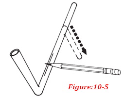
Bend Direction Mark
One method for keeping track of changes in plane is to use a
longitudinal or lengthwise bend direction mark. (See Figure 10-5 above)Put the mark on the
side opposite the direction in which you wish to bend. When you put the tube in
the bender, center the mark face up in the groove of the radius block. (See
Figure 10-6)This will insure that you bend in the correct direction. It also gives
you a reference mark in case you must leave your work unfinished.


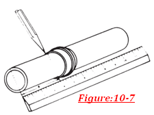
Marking the Tube
Whenever you make a mark on tubing, use a sharp pencil. Use a ferrule
as a guide to make measurement marks all the way around the tube so that the
mark is always visible. (See Figure 10-7) Don’t use grease pencils or crayons
as these make too wide a line which can easily affect accuracy.
Measure and Mark
Never use a sharp tool to scratch marks onto tubing. Scratches create
points where corrosion or stress
concentration can ruin or dangerously weaken the tube.
Rules for Positioning Tubing in
Bender
A line which is tangent to the desired angle mark on the radius block
and which passes through the measurement mark at the centerline of the tube, is
used to control the distance between bend centerlines. (See Figure below)


Tube Positioning Rules
90° angles - tangent
flush with length mark (refer to dotted line xy tangent to radius block @ 90°
fig. 10-8 (above).
Angles less than 90° - tangent intersects length mark at centerline.
Angles less than 90° - tangent intersects length mark at centerline.
Angles more than 90°
- position for a 90° bend and continue on to desired angle, i.e. 135°, 145°.
(i.e. Length mark @ 90° on link member)
Horseshoe or u-bends – measure first leg, position for 90°, bend around to 180°.
Horseshoe or u-bends – measure first leg, position for 90°, bend around to 180°.
Compensate for springback:
a. Test a piece of
the material before you start fabricating a line to see how much it springs
back on a 90° bend.
b. Overbend by the
amount of springback. For example, if the material springs back 3° on a 90°
bend, bend to 93° to secure a finished 90° bend, or to 46-1/2° to obtain
finished 45° bend. This works especially well with large heavy-wall tubing.
c. Remember, it is
always better to underbend slightly. You can always bend a little more if
needed, but it’s almost impossible to remove or straighten a bend, especially
with large, heavy-wall tubing. REMEMBER - A TUBE BENDER BENDS -IT CAN NOT UNBEND.
When bent, tubing seems to stretch or pick up length. This is because
it takes a curved shortcut across the inside of the angle. A good “rule of
thumb” for most standard tubing materials and radius blocks is that the tubing will
stretch approximately one tube diameter for each 90° bend.
Always try to bend in the same direction - away from the original
starting end. If you reverse the direction of bending (bending towards instead
of away from the original starting end) you will “trap” the stretch. Thus, if you unknowingly make a reverse bend of 90°,
you will trap the gain, in table 10-1 (approximately one tube O.D.) and
increase your length between bends by that amount. If bend direction for either
45° or 90° bend must be reversed, subtract the “gain” amount listed in table
10-1.
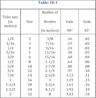
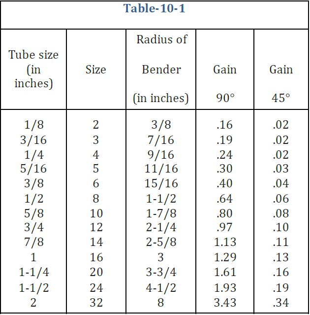
While our rule of thumb is approximately correct, the amount of stretch
is related to the diameter of the radius block used. This chart (Figure 10-11)
gives the accurate increase in length that occurs with the most commonly used
sizes of radius blocks. As long as you measure and bend with the tube inserted
from the left, and measure centerline, “pickup” will not affect your actual center-to-
center measurement.

1.
Some radius blocks may differ. Consult
individual radius block manufacturers for details on other radius diameters.
2.
For
metric tubes the size and radius can be computed in the similar way.
You may pre-measure a series of bends. Measure the first bend from the
end of the tube, the correct length. Compensate for each bend after the first
by subtracting the amount of gain from your chart for each 90° of bend to allow
for stretch (Figure 4-11). Always custom measure for the last bend.
“Rule of Thumb” Method
Compensate each measurement after the first by subtracting the gain
listed in table 10-1. Best Way to Measure For maximum accuracy,
measure and bend exactly for each individual bend in the tubing line. We recommend the practice of Measure and Bend then again Measure and
Bend, etc.

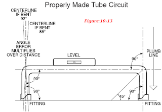
In a well made tubing circuit or line, bends are accurate, measurement
exact. The run is plumb, square and level. Tube ends rest firmly in the
fittings and entry into the fittings is straight. Straight tube entry is very
important to insure that fittings are not under stress and can be assembled
without leaks. (See Figure 4-13 below)
Remember too, that length magnifies bend angles errors. If the leg
following the bend is fairly long, an error of 1° may result in the tube line
missing the desired point completely.

Recommended Free Tubing Lengths
It is important to consider the length of tubing from the end in the fitting
body to the beginning of the
bend. Table: 10-2 lists the recommended lengths “L” and “D” for various
sizes of tubes.


Figure A shows an ideal bend. Bends with little or no flattening are
produced when correct equipment and methods are employed; when proper
consideration is given to corelationship of the radius of the bend, material
wall thickness and hardness of the tube. Figure B shows a flattened bend, caused by
trying to bend too short a radius, or bending smaller diameter tube in larger
radius block. Figure C shows a kinked and flattened bend, caused by the tube
slipping in the bender, or by using non-annealed tubing. Tubes must be firmly
clamped by clamp block to prevent slippage during bending process. Figure D shows
a wrinkled bend, sometimes produced when thin wall tube is bent. Breakage will sometimes
occur when mandrel is too far forward in tube, or when too short a radius is attempts
with hard tube.


Offset Bends
To form a tube offset, it is obviously necessary to make two bends.
With the tube benders, it is easy to make double 45° bends. To make an offset
bend simply follow the “Offset Bend Allowance” steps below to determine the
proper distance between the two 45° bends. Here’s the procedure.


STEP 1 First, determine the total amount of offset required (dimension
“F” in the diagram).
STEP 2 Next, determine the angle of offset - 30° or 45°. The latter (45°) is recommended because benders are calibrated for 45° bending.
STEP 3 Figure the length of the tube required to meet your offset requirements (“L” dimension) in the diagram. For 30° bends multiply desired offset “F”x 2= 30° offset dimension “L”. For 45° bends multiply desired offset “F”x 1414=45° offset dimension “L”.
STEP 4 Determine where you want the offset bend of the tube to start; and make a reference mark (A). Now measure off the “L” dimension (determined in Step 3), starting from the reference mark and make a second mark (B). You are now ready to make the bends.
STEP 5 Align mark (A) with reference mark 45° on bender shoe handle (measurement end to the left) and proceed with first bend. Then align (B) with 45° mark and make second bend in proper direction (measurement end to the left). Follow previous detailed instructions for making 45° bends in one plane.
Routing of lines is probably the most difficult yet most significant of
these system design considerations. Proper routing involves getting a
connecting line from one point to another through the most logical path. The
most logical path should:
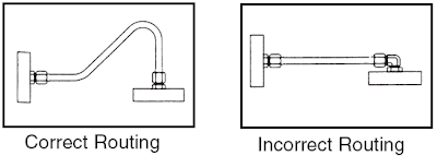
Avoid excessive strain on joints - A strained joint will eventually
leak.


Allow for motion under load - Even some apparently rigid systems do
move under load.


Get around obstructions without using excessive amount of 90° bends.

Pressure drop due to one 90° bend is greater than that due to two 45°
bends.
Keep tube lines away from components that require regular maintenance.

Have a neat appearance and allow for easy trouble shooting, maintenance and repair.

Following additional guidelines for the installation of copper tubes
should be followed.
· Generally long runs of copper tubes are not used
because of slow response.
·
Therefore, extension of tube length is not
required. However, if it is needed union is used (instead of brazing and
welding).
·
Separation is being maintained between the
pneumatic tubing used for redundant valves/instruments.
·
Because of response time considerations 6 mm
tubes are for short distances whereas 10 mm tubes are used for air supply
connections.
·
Pneumatic tubing for redundant instruments
should be taken from different supply headers.
·
Considering the strength and hardness of copper tubing,
brass tube fitting becomes the preferred choice. The tube fitting that is used
is Brass compression type single ferrule tube fitting.
·
The installation procedure of brass tube fitting
is more or less similar to that of SS tube fitting. However galling problem of
straight threads is not there to that extent as that of SS tube fittings.
·
Moisture free instrument air is recommended from
the consideration of corrosion of tubing.
·
Tubing should not be laid at a place where human
or machine movements are expected. As these tubes are soft they may get
damaged.

bend. Tests demonstrate that the bursting strength of a bent copper
tube can actually be greater than it was before bending. Because copper is readily
formed, expansion loops and other bends necessary in an assembly are quickly
and simply made if the proper method and equipment are used. Simple hand tools
employing mandrels, dies, forms and fillers, or power operated bending machines
can be used. Both annealed tube and hard drawn tube can be bent with the
appropriate hand benders. The proper size of bender for each size tube must be
used. For a guide to typical bend radii, see Table10-3. The procedure for
bending copper tube with a levertype hand bender is illustrated in Figure below

Soldered joints, with capillary fittings, are used in plumbing for
water lines and for sanitary drainage. Brazed joints, with capillary fittings,
are used where greater joint strength is required or where service temperatures
are as high as 350°F. Brazing is preferred, and often required, for joints in
refrigeration piping.
Mechanical joints are used frequently for underground tubing, for
joints where the use of heat is impractical and for joints that may have to be
disconnected from time to time. Copper tube may also be joined by butt-welding
without the use of fittings. Care must be taken to use proper welding procedures.
good information.
ReplyDeleteThank you for effort and information
ReplyDeleteThanks so much
ReplyDeleteVery good!!👏👏👏👏👏
ReplyDeletewe are online transporter and we provide truck for loading material we are best in industry cause we are very low cost service provider
ReplyDeleteBangalore to Delhi transporter services
Bangalore to Ahmedabad transporter services
Bangalore to Mumbai transporter services
Bangalore to Hyderabad transporter services
Bangalore to Kolkata transporter services
transporters in delhi
you are post so, nice information. Thanks for shearing this post.
ReplyDeletemedium duty machines in Kolkata
Vibratory Deburring in kolkata
Nice information and thanks for posting its really nice sharing Commercial Drain Cleaning Repair
ReplyDeletelarge variety of original developments ...
ReplyDeleteDie Casting Machines Exporters
Exporters of die casting machine
Manufacturers of die casting machines
Bending Machine
Pressure Die Casting Machines
Die Casting Machinery
Die Casting Machines Manufacturers
Pressure Die Casting Machine
Zinc Die Casting Machine
Aluminum Die Casting Machine
Die Casting Machine
High Pressure Die Casting Machine
PLC Pipe Bending Machine
Tube Bending Machine
Pipe Bending Machine
Three Axis Pipe Bending Machine
Mandrel Pipe Bending Machine
Hydraulic Pipe Bending Machines
Single Axis Pipe Bending Machines
Rapid Flow established in 1979 and offers a wide range of world-class machines for various applications.
ReplyDeleteOur Services :
Die Casting Machines Exporters
Exporters of die casting machine
Manufacturers of die casting machines
Bending Machine
Pressure Die Casting Machines
Die Casting Machinery
Die Casting Machines Manufacturers
Pressure Die Casting Machine
Zinc Die Casting Machine
Aluminum Die Casting Machine
Die Casting Machine
High Pressure Die Casting Machine
PLC Pipe Bending Machine
Tube Bending Machine
Pipe Bending Machine
Three Axis Pipe Bending Machine
Mandrel Pipe Bending Machine
Hydraulic Pipe Bending Machines
Single Axis Pipe Bending Machines
Alfazal Engineering providing services for Cable tray, Tower tray, and other sheet metal work at very economical prices with the best delivery time all over Pakistan. tower trays for the refinery. Cable Tray street lighting poles manufacturer in Pakistan by Al-Fazal Engineering Perforated Cable Tray Made of Sheets With Perforation on the based. Cable Gland, Cable tray distributor in Pakistan. We are available for your support 24/7 and 100% guarantee for quality. We never compromise in the quality of the cable tray and other products.
ReplyDeleteCable tray
Thank you very much for your detail explanations,.
ReplyDeleteHi,
ReplyDeleteThanks for sharing such amazing news. You cn also check out Hot Tapping Machine Suppliers.
Focus on the consumer electronics charging products such as Power banks, Wireless Charge, Power Adaptors. We create products that help people realize the power of technology and make people’s lives better, easier and more fulfilling.
ReplyDeleteFocus on the consumer electronics charging products such as Power banks, Wireless Charge, Power Adaptors. We create products that help people realize the power of technology and make people’s lives better, easier and more fulfilling.
ReplyDeleteFocus on the consumer electronics charging products such as Power banks, Wireless Charge, Power Adaptors. We create products that help people realize the power of technology and make people’s lives better, easier and more fulfilling.
ReplyDeleteFocus on the consumer electronics charging products such as Power banks, Wireless Charge, Power Adaptors. We create products that help people realize the power of technology and make people’s lives better, easier and more fulfilling.
ReplyDeleteGood post! We are linking to this particularly great post on our website.
ReplyDeleteStainless Steel Corner Trim
Corner Profile
Stainless Steel Decorative Trim
Relocation for companies and private individuals with a free viewing and preliminary discussion. Your house or office furniture dismantling and furniture assemblies are carried out by a packing and assembly specialist
ReplyDeletePackers and movers in Sector 22
Packers and movers in Sector 44
Packers and movers in Sector 39
Packers and movers in Sector 137
Packers and movers in Sector 19
Packers and movers in Sector 18
-----------------------------------------------------------------------
ReplyDeletewww.iceway.fun
-----------------------------------------------------------------------
Englisch
Not sure what to do in your spare time? Visit iceway.fun, we have a wide range of more than 1000 free unique arcade games. In addition, we are the only game site in Europe with a huge book collection. So what are you waiting for? see you at iceway.fun
Arabic
لست متأكدا ماذا تفعل في وقت فراغك؟ قم بزيارة iceway.fun ، لدينا مجموعة واسعة من أكثر من 1000 لعبة أركيد مجانية فريدة من نوعها.بالإضافة إلى ذلك ، نحن موقع الألعاب الوحيد في أوروبا الذي يحتوي على مجموعة ضخمة من الكتب. فما تنتظرون؟ اراك في iceway.fun
Chinese
不知道在業餘時間做什麼?訪問iceway.fun,我們擁有超過1000 款免費獨特的街機遊戲。此外,我們是歐洲唯一擁有大量圖書收藏的遊戲網站。你還在等什麼?在iceway.fun見
French
Vous ne savez pas quoi faire pendant votre temps libre ? Visitez iceway.fun, nous avons une large gamme de plus de 1000 jeux d'arcade uniques gratuits. De plus, nous sommes le seul site de jeux en Europe avec une énorme collection de livres. Alors qu'est-ce que tu attends? à bientôt sur iceway.fun
Russian
Не знаете, чем заняться в свободное время? Посетите iceway.fun, у нас есть широкий выбор бесплатных уникальных аркадных игр, более 1000. Кроме того, мы являемся единственным игровым сайтом в Европе с огромной коллекцией книг. И так, чего же ты ждешь? увидимся на iceway.fun
Spanish
¿No sabes qué hacer en tu tiempo libre? Visite iceway.fun, tenemos una amplia gama de más de 1000 juegos de arcade únicos y gratuitos. Además, somos el único sitio de juegos en Europa con una gran colección de libros. ¿Entonces, Qué esperas? nos vemos en iceway.fun
-----------------------------------------------------------------------
Take me to the best game site in Europe
-----------------------------------------------------------------------
Great information on blog. keep posting.
ReplyDeletewe sell welding torch manufacturer in Jalandhar.